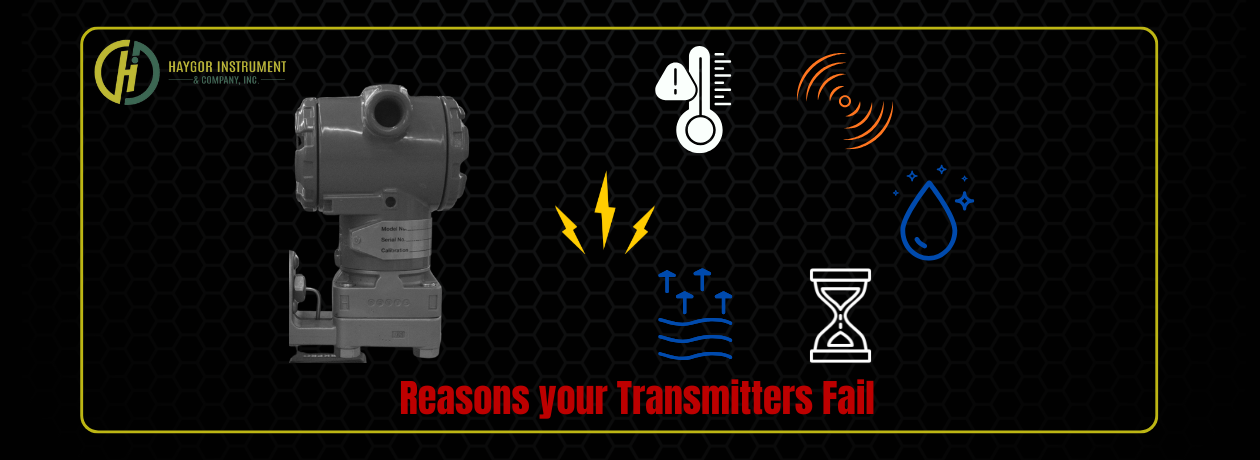
4 Reasons Your Pressure Transmitters Fail and What Each Error Message Means
Pressure transmitters are essential for precise process control in various industries, including oil and gas, as well as food production. Yet even the most robust devices can fail if exposed to harsh conditions or neglected maintenance. Recognizing why these failures occur and how to interpret diagnostic messages can significantly reduce downtime and improve safety.
Major Causes of Pressure Transmitter Failures
1. Mechanical Stress
- Overpressure or Physical Impact
- Exceeding the rated pressure or subjecting the transmitter to sudden mechanical shocks can permanently deform the sensing diaphragm, leading to inaccurate reading or complete failure.
- Vibration and Shock
- Persistent vibration (for example, near large pumps or motors) can loosen internal connections or crack solder joints. Proper mounting and vibration isolation are essential【ISA-RP12.6†International Society of Automation].
- Pressure Spikes or Pulsation
- Rapid surges in process pressure accelerate wear and cause sensor drift.
2. Environmental and Chemical Exposure
Corrosive Media
- Aggressive fluids or gases can gradually corrode wetted parts. Therefore, it is essential to select an appropriate diaphragm material, such as Hastelloy or Tantalum, for corrosive service (API 551, American Petroleum Institute). Installing electrical housing cover O-rings can also help prevent moisture from reaching the electronics or connection terminals.
Extreme Temperatures
- Excessive heat can degrade electronics while freezing or cryogenic conditions may damage internal fill fluids or membranes.
Moisture Intrusion
- High humidity or water ingress often leads to internal corrosion or short circuits. IP66/IP68-rated housing and proper cable sealing help mitigate this risk.
3. Electrical and Installation Issues
Incorrect Application
- Using a transmitter designed for benign fluids in abrasive slurries or high-pressure steam service will significantly shorten its life.
EMI/RFI Interference and Wiring Faults
- Electromagnetic interference, poor grounding, reversed polarity, or short circuits can cause erratic readings or total failure. Following IEC 61326 guidelines for shielding and grounding is recommended [61326†International Electrotechnical Commission].
Component Aging
- Over years of operation, electronic components naturally drift out of specification.
4. Operational and Maintenance Gaps
Calibration Drift
- Loss of calibration, sometimes referred to as zero drift, leads to inaccurate measurements and false alarms.
Deferred Maintenance
- Skipping periodic inspections allows small issues to escalate and become more significant over time. Industry best practices suggest calibration at least annually, or more often in critical services [ISA-TR67.04.01†ISA Standard].
Decoding Common Diagnostic Messages
Two widely used transmitter families illustrate how different manufacturers communicate failures.
Emerson Rosemount 3051
Typical display messages include:
- FAIL BOARD – Electronics board fault; replace the board.
- XMTR MSMTCH – Incompatible sensor module; install a matching module.
- NO P UPDATE – No pressure signal; inspect sensor cable or replace sensor.
- FAIL SENSOR – Sensor module failure; replace module.
- NO T UPDATE – Temperature signal missing; check cable or sensor.
Maintenance alerts such as STUCK BUTTON, POWER ADVISE, or Plugged Line indicate specific issues ranging from a jammed keypad to a blocked impulse line.
Honeywell ST 700–800 Series
These transmitters signal errors through out-of-band 4–20 mA currents and FOUNDATION Fieldbus diagnostics:
- PV Not Updating (5 s) – Outputs burnout current; power cycle to recover.
- Loop Current Abnormal (40 s) – Burnout current; power cycle to recover.
- Electronics Fault (within 14 min) – Burnout current; power cycle to recover.
- Fieldbus Faults – Status bits, such as BLOCK_ERR, reveal internal issues, view block diagnostics for details.
Practical Prevention Tips
- Proper Selection – Match transmitter materials and pressure rating to the process media and operating conditions.
- Protect Against Vibration – Use vibration-damping mounts and avoid direct installation on piping that experiences strong pulsation.
- Follow Electrical Standards – Ensure proper grounding and shielding in accordance with IEC 61326 to minimize interference.
- Routine Calibration & Inspection – Establish a calibration schedule and inspect impulse lines for plugging or moisture.
How the Thermal Guardian Prevents Pressure-Transmitter Failures
While careful installation and routine maintenance are essential, Haygor’s Thermal Guardian provides an extra layer of protection that directly targets the root causes of pressure-instrument failure.

Active Thermal Management
Thermal Guardian maintains a stable enclosure temperature, shielding transmitters from extreme heat or cold that can crack diaphragms, damage fluids, and accelerate electronic drift. By keeping conditions within a controlled range, it dramatically reduces failures due to ambient or process-temperature swings.
Protection Against Moisture and Corrosion
The system’s sealed, heated housing prevents condensation and humidity ingress, two of the most common triggers for internal shorts and corrosion. This eliminates the hidden moisture damage that often leads to sensor-module replacement.
Vibration and Shock Buffering
Built with robust mounting options and insulated panels, Thermal Guardian dampens vibration and absorbs mechanical shock. This minimizes loosening of solder joints or terminal connections, which are frequent culprits in zero drift and intermittent signals.
Lower Maintenance Burden
Because the unit continuously regulates temperature and humidity, transmitters inside Thermal Guardian experience less calibration drift and fewer component failures. Plants can extend calibration intervals, reduce emergency callouts, and lower lifecycle costs.
Real-World Results
Facilities using Thermal Guardian report significant reductions in transmitter downtime and more consistent data accuracy, even in demanding outdoor or process-side environments.
The Bottom Line
Integrating Thermal Guardian enclosures with your pressure transmitters transforms reactive maintenance into proactive protection.
By controlling temperature, humidity, and vibration, it directly addresses the key mechanical, environmental, and electrical stressors that lead to premature transmitter failure, helping you maintain reliable measurements and uninterrupted operations.
